I take absolutely no credit for this tutorial, i just find it very helpful for starters to see this. Credit to [JED] from Team xecuter for tutorial. Also credit to Streamah on TTG for making this great post, I just edited it for XboxMB.
Installing The Nand-X (Xenon, Zypher, Opus, Falcon, Jasper)
Parts List :
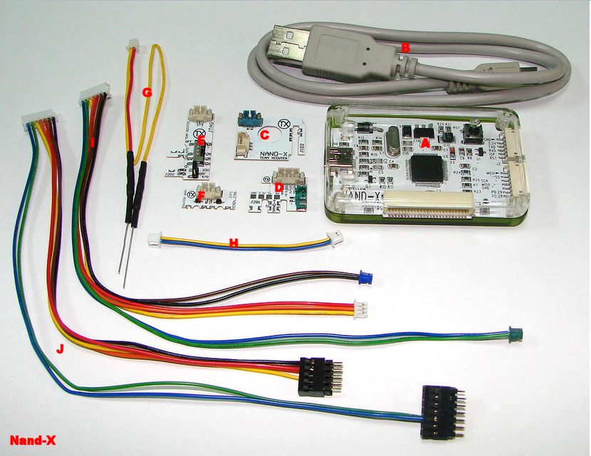
A : Nand-X Nand Reader and Writer
B : Mini B (5 Pin) Usb Cable
C : Quick Solder Pad For J1D2 (Next To the Nand)
D : Quick Solder Pad For J2D1 (Next To Video Cable Input)
E : Quick Solder Pad For J2D2 (JTAG) (Closet Debug Port To Gpu and Heatsink)
F : Quick Solder Pad For J1F1 (JTAG)(Xenon Only) (Bottom Left 6 Pins)
G : JTAG Cable For (Zypher, Opus, Falcon, Jasper ONLY !)
H : Quick Solder Cable Joiner For Part E and F (For Complete Circut)
I : Quick Solder Pads Cable / Joiner Into Nand-X Nand Reader and Writer (Only)
J (3 Parts) Part 1 = Cable, Part 2 and 3 = Little Pin Blocks
(Picture = Nand-X Retail Final Post)
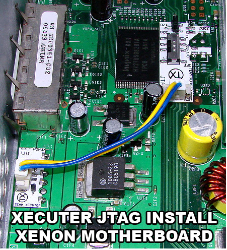
Part 1 : Installing JTAG
Xenon (ONLY !)
[details=Open Me](Xecuter Has Allready Made a Picture)
When installing use these parts F and E,
To Install Remove the White piece of plastic on the bottom of the quick solder pads to make them sticky and Align them like so in the picture and grab your soldering iron. When soldering just touch the holes and drag your iron across to create a connection. After You have soldered them in connect the yellow and blue cable as below to create a completed JTAG circut (Part H ^)
 [/details]
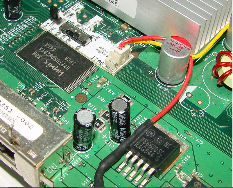
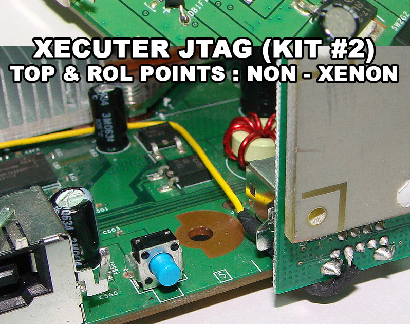
Zypher, Opus, Falcon, Jasper
[details=Open Me](Xecuter Has Already made a Picture)
when installing this you will need parts (Labeled Above) E and G.
firsly get Part E and remove the white piece of plastic then align them like so in the bottom picture.
When soldering The Pads onto the motherboard just grab a bit of solder and then touch it to the hole on the motherboard and then drag your iron (NOT HARD JUST A MOVEMENT) to create a connection bewteen the board port and quick solder pad.
To install the cable simply look below and get part G,
The White Block Connector goes into the Part E, and the smallest end of the cable needs to be soldered to Point DB1F1 (Bottom Left Near Eject) and the longest end just solder it to the ROL (Ring of Light) connector on the Front (Second Line, Second Point) as below
[/details]
Part 2 : Installing Nand-X Quick Solder Pads
Open Me
Finding a replacement as soon as this is posted.
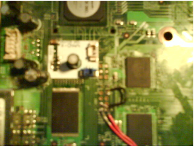
Installing Part C (Quick Solder Pad J1D2)
[details=Open Me]As below you will see the blue connector is pointing down towards the front of the console,
Remove the white piece of plastic on the bottom of the pad to make it sticky and align it so you have the just touching in the the holes,
Then once in place just grab your soldering iron,
To solder pads just grab a length of solder and touch the little hole on the motherboard and drag (NOT HARD JUST A SWIFT MOVEMENT !) to Join the Pad to the motherboard.

[/details]
Installing Part C (Quick Solder Pad J2B1)
[details=Open Me]Now like below just remove the piece of plastic to make sticky and align it like so :
Green port to the left / pointing towards dvd sata and power.
solder all of the pads for this one (Ignore the TX, Rx 3.3v and GND pads there for Devs)

Now your all done with soldering !
I take Part I and join blue connector and white connector to J1D2 and green connector to J2B1 (Like Below)
[/details]
Part 3 : Reading and Writing Nand
[details=Open Me]Now Im not going to explain the reading as it is explained in the nandpro documention. but when all soldered in etc and have the nand-x plugged into the computer just open nandpro and turn the nand-x on via clicking the black button and usual commands apply.
[/details]
How to use nand - x
Plugging into Computer
[details=Open Me]-you need the nand-x wired in
-the console power supply plugged in but console not powered on (light on brick orange)
-plug the nand-x in to the pc usb
-when prompted for a driver navigate to the nandpro directory, it should then install the correct driver.
[/details]Now to Dump Nand[details=Open Me]-To do this you need to open a dos window, press windows key or start, click run in the box type cmd.
-A dos box will open now we need to go to the nand pro directory
-Type cd… (do this as many times until you only see c:)
-Type cd nandpro
-You now see c:/nandpro
-Now we need to type nandpro usb: -r(16/256/512) dump.bin don’t include the brackets and select the correct size for your nand.
-You should then have a flash config of one of the following, if not it ain’t going to work.
01198010 - Xenon, Zephyr, Opus, Falcon
00023010 - 16mb Jasper
008A3020 - 256mb Jasper
00AA3020 - 512mb Jasper
Don’t know how true this is but if your nand is a samsung it’s 512 (just a rumour)
-You should then be prompted to press any key, do it.
The dumping will begin, depending on the nand (size can take 5 mins+) you may have some bad blocks during the read don’t worry this is quite normal as the nand sometimes has bad blocks that are moved to a reseved area, (i’ll cover this more later)

The picture above shows a successful dump of a 16mb nand with one bad block read error. it had read from 0 to 3ff (400 blocks in hex).
[/details]
Create Another Dump
[details=Open Me]Lets make another to compare, this is very important, this is very much measure twice cut one. If we foobar our nand then we will have all sorts or trouble in the future trying to get the box to work again we will loose mac address’s, machine serial (not the one on the case) and nettwork info, drive keys you get the picture so take time and do this.
Make another dump,
nandpro usb: -r(16/256/512) dump2.bin
once you have two dumps, lets compare the files we have
fc dump.bin dump2.bin
If there are no differences then we can proceed if you get differences then do another dump called dump3.bin and compare with the other two dumps, once you have two identical dumps then proceed.[/details]
[b]Now we have a Dump[/b]
[details=Open Me]-First step now we have a dump it to check the cb version.
-We need a program called 360 flash dump tool v0.94(now v.95)
-Open it up,

The above pic shows the various boot loader stages we’re only interested in the 2bl cb one. dont worry about the right hand side showing bad unknown kv at the minute.
1888, 1902, 1903, 1920,1921: xenon
4558: Zephyr 4580 <— try falcon smc for this unit.
5761, 5766, 5770:falcon
6712, 6723: jasper
Any of the above is good to go.
any of the below Non-Exploitable CB Versions (CD = 8453 for all of them)
Xenon: 1922, 1923, 1940
Zephyr: 4571, 4572, 4578, 4579
Falcon/Opus: 5771
Jasper: 6750[/details]
Halfway
[b]Decrypting Dump[/b]
[details=Open Me]We have a full dump now but we need to decrypt it to make sure it is a working dump, for this we need the cpu key, to get this we will need to use xell.(ous)
with your dump.bin we are going to need the encrypted key vault, to get this type
nandpro dump.bin: -r(16/256/512) kv.bin
we now have you key vault called kv.bin[/details]
[b]Writing Xell to Nand[/b]
[details=Open Me]now to write xell to the nand and get the cpu key,
-you will need xell for your motherboard revision
-xellous (keeps it easy for noobs)
-and your kv.bin (this is different for every motherboard so must be the one from the board)
flash xell (free60 version)to the console you are flashing a file approx 1.3mb in size double check this before you start flashing so not to overwrite the rest of the nand.
MAKE SURE TO HAVE THE VERSION FOR YOUR BOARD
zephyr would be
nandpro usb: -w16 zephyr_hack_updxell.bin 0
xenon would be
nandpro usb: -w16 xenon_1921hack.bin 0
big block jaspers (edit the 256/512 to suit)
nandpro usb: -w256/-w512 jasper_6723_hack_for_256mb_512mb.bin 0
etc…
once you have flashed this then flash the kv back
Then flash your KV with the following command, it’s the same for all versions of motherboards:
nandpro usb: -w16/256/512 kv.bin 1 1
It’s very import for you to flash your key this enables xellous to decrypt the info stored in nand and display it.
update the xell with xellous
open the xellous rar image and extract xell-1f.bin
nandpro usb: +W16 xell-1f.bin 40
once this is done remove the power cord and wait 30 seconds or so,
plug in the composite av lead and the network cable,
If it has worked correctly then after the blue screen with writing you should see at the bottom the dvd key and the cpu key displayed for you, and then a line httpd listen: make a note of the ip number after that, (you can just write down the cpu number but this takes the human error out of the equation)
open up firefox on your pc and type in that ip address
you should be prompted with a white screen with some options.
click download for fuses this gives you a txt file with cpu key and dvd key.
once you have the info power down the console.
[/details]
[b]Making the freeboot dash[/b]
[details=Open Me]We now have a full dump, cpu key info, key vault. we are now ready to make the new updated dash.
-first off open up 360 dump flash tool, put in your cpu key from the text file or the one you have written down, open up you dump and now the text on the right will now give you cpu key dvd key serial etc. If it is there click the bad block box and note the bad blocks in the dump (this is not visible if there are no bad blocks)
Now to make the free style dash we need
-dump.bin
-9199.zip
-freeboot 0.032
First extract free boot to freeboot directory inside this should be 3 folders (bin data temp,ibuild) and readme, you will need to find and put a copy of libeay32.dll in there too, put a copy of you dump.bin in there too. you’ll need to google for the 1bl key.
1. Extract your original image
Extract your original 7371 [recommended but not necessary] image with the following command:
ibuild.exe x -d temp\ -p [cpu key] -b [1bl key] dump.bin (dont include the square brakets)
2. Extract “9199.zip” archive
Extract the contents of the “9199.zip” archive into the “data”
directory.
3. Copy these files from “temp” to “data” directory
[i]- crl.bin
- crl.bin.meta
- extended.bin
- extended.bin.meta
- kv.bin
- odd.bin
- odd.bin.meta
- secdata.bin
- secdata.bin.meta
- smc_config.bin[/i]
4. Patch SMC
Put a patched “smc.bin” in the “data” directory. The easy way to grab this is to grab a copy of xbr for your console rev, open it in flash tool and extract the xbr, you need the smc enc.bin (encrypted) not smcenc.bin rename it to smc.bin and put it in the data folder.
If you are using one of the new smc by blackaddr (bug fix new ports) (here Get help with new SMC i/o ports and bugfix here) now is a good time to put it in your build, as it is encrypted with the rest of your build.
- Choose your patches in the “bin” directory there are 2 directories:
“patches [full mem editing]” and “patches [xb1 compatibility]”.
If you want xbox1 emu use “patches [xb1 compatibility]”,
if you want to be able to have full memory access use the other.
6. Create the freeBOOT image
Finally, create your freeBOOT image with this command:
ibuild.exe c freeBOOT -c [console] -d data\ -p [cpu key]
-b [1bl key] bin\image.bin bin\fuses.bin
Replace [console] with either “xenon”, “zephyr”, “falcon”, “jasper”,
“jasper256” or “jasper512” [without quotes] and square brackets
example
ibuild.exe c freeBOOT -c Xenon -d data\ -p 123456789012345678 -b 1234123412341234 bin\image.bin bin\fuses.bin
You will now be gifted with two new files in the bin folder
one called image.bin and one called fuses.bin, the fuses is the details of keys etc we already have this to be able to get this far so ignore it.
we need to flash the image.bin to the console.
nandpro usb: -w16/256/512 image.bin
It will now Write the new image to the nand, after writing unplug the console for 30 seconds, plug it back in and reboot, should boot up, if you get
no power no booting, the smc was wrong,
e79 try another flash
e71 recheck the solder points.
If all has gone well, go to your system setting and check the kernel version will now be 9199 job done.[/details]
Anyway, felt this post would be useful seeing how everyone keeps bricking their jtag trying to upgrade dashboard. It’s simple tbh. 8O
These only cost 45$ and for advertising purposes all i can suggest is searching on google “Nand -x Team executer”
You will get good results and follow the links.
Hope you all enjoy this post 