[size=30]This is a 3 Part Text Tutorial on how to make a Portable Xbox 360 Laptop
If you have any questions please either PM me or send me a message on AIM [/size]
[size=30]
AIM = airbornllama
[/size]
My friend (Aden) and I posted this on TTG as well!
I am going to be making more of these and selling them. The reason for this post is for those who want one, but want to know how its made, and maybe make one themselves!
[size=20]Credits to Ben Heck
This takes a very long time to make, and each part is very long, (too long for one thread), so I had to split it up into 3 different threads (links will be on this post).
[/size]
How To Make An Xbox 360 Laptop Part 1
(Text Tutorial with Pics)
---------------------------------------- [details=Text Tutorial Part 1]
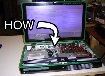
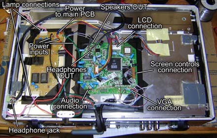
[size=25]The making-of How-To for the Xbox 360 laptop will be in three parts. In today’s segment we’ll discuss the parts list, stripping down an Xbox 360 motherboard, and modding / reattaching the DVD and hard drives. The next installment will cover case design, construction and hacking the LCD display, as well as wiring the video. Part 3 will then describe wiring all the separate parts together, troubleshooting, and finishing up the unit. Full design files will be including along the way. Let’s take a look and prep to get started!
Can’t make an Xbox laptop without some parts, so let’s see what we’ll need.[/size]
Parts list
[size=25]
-
Xbox 360 Premium system - Or whichever version you wish. With the Elite you could, in theory, make an HDMI-DVI converter and input that into a LCD. The model LCD we used had DVI but, of course, the XBox we used is still analog. Rats.
-
Westinghouse LCM-17x1 17-inch widescreen monitor - Same as on the first Xbox laptop we did in 2006. However, by the time we started construction on the second laptop, these have all but disappeared from the stores. Thankfully there were some still available online, namely from places like eBay. Alternatively, most 17-inch widescreen LCD monitors should work. They’re plummeting in price since the 19-inch LCDs are dirt cheap these days. This monitor also gives us a sound amplifier and built-in speakers we can use. The resolution of this screen is 1280 x 768 so it fits the high def resolution of the 360 nicely.
-
Xbox 360 WiFi module - Here’s half the cost of the project alone! Ha ha, we kid, we kid. But when you’re making a “portable” unit, the less wires the better. I’ve seen these adapters sell used for as low as the “bargain” price of $75. I’ve heard certain model “thumb” USB WiFi adapters work, but we haven’t tested any as of yet.
-
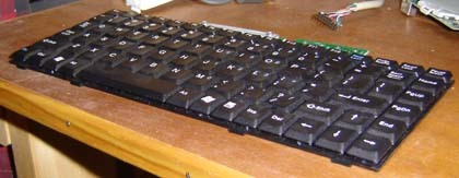
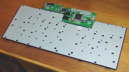
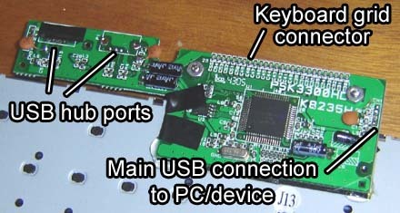
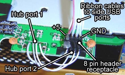
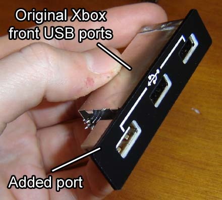
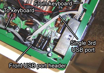
Small, flat USB keyboard - we suggest one such as this. If you can find one with a built-in USB hub that’s even better since you’ll actually gain a USB port by using the keyboard.
-
Male headers - These are used to interconnect things between circuit boards. You can pull them off old motherboards or buy them new.
-
Ribbon cable - As usual I’d suggest the type from old floppy drives and IDE disks. However, for rewiring SATA connections it’s best to have thin (as in Ultra ATA 33 and up) solid-strand wire. You can tell if it’s solid or stranded by bending the cable – solid wire cable holds its shape much better than stranded.
[/size]
Tools you’ll need today
[size=20]
-
Soldering iron - As usual we suggest a low wattage type to avoid damage to parts.
-
Desoldering iron - To remove parts, and is also useful to solder large items that the lower wattage iron can’t handle.
-
Dremel tool - With the ever-important cutoff wheel to slice up things.
-
Wire clippers, small screwdrivers and tweezers - All very handy.
-
X-Acto knives - Again, quite useful for doing delicate (and sometimes not so delicate) hacking work.
-
Multimeter - Or “voltage meter”, whatever you’d like to call it. Very useful for detecting circuits to discover pinouts.
[/size]
[i][/i]Stripping down an Xbox 360 motherboard[b][/b]
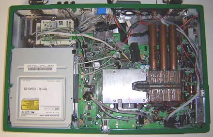
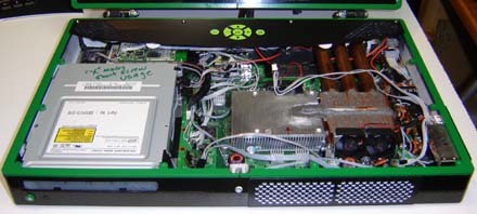
I’m not going to cover how to take apart the somewhat Pandora’s Xbox-esque 360 case since it’s covered elsewhere on the 'net. We’ll start by assuming you have it disassembled and down to the motherboard and drives.
[i][/i]Removing parts from the motherboard[b][/b]
[size=25]We don’t need to get into how to desolder in this article since we’ve covered it before. Some tips on removing these parts from the motherboard:
-
It is important to note that the Xbox 360 is RoHS compliant, meaning it uses unleaded solder.
-
In general it’s tougher to desolder parts in the RoHS world, so for best results apply some new solder onto a pin, then heat it with the desoldering iron for longer than you normally would (so about 4 seconds) before sucking up the solder.
-
Be especially careful with pins that connect to inner ground or power planes, they’re also difficult to remove. This is also true of the ground connections on a jack that connect to the main surface of the board, such as a USB jack.
-
Use a clean, brand new desoldering iron tip for best results. Heat up a pin for a little longer than normal to ensure all the solder in the through-hole is melted before you try and suck it up.
Side RoHS conspiracy theory - While we were doing the Wii Laptop hack we noticed it was very easy to desolder parts off the motherboard, unlike most other modern electronics. Could the Wii have been non-RoHS compliant, thus explaining the shortages?[/size]
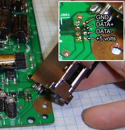
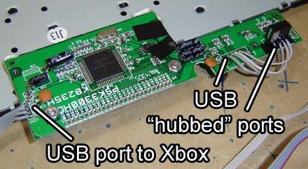
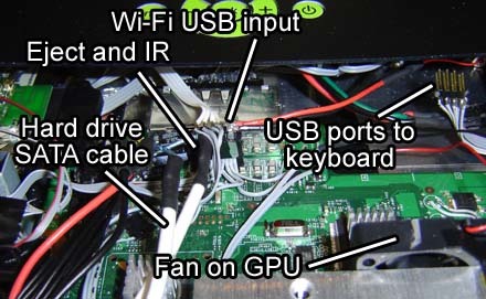
The front USB ports. It connects with two rows of pins (for the USB signals) and metal tabs off the shielding on the side. The best way to get this sucker loose is to rock it back and forth slightly while heating the large metal mounting tabs. It also helps to chop off any plastic posts from the plug that are going through the board. The photo above shows the pinout for future reference. The left column of pads is port 1, the right column is port 2.
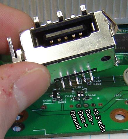
Here’s one of the memory card connectors. It uses a pinout much like USB, but uses +3.3 volts instead of 5. Since these take up a decent amount of space it’s best to remove them, but use the pinout above should you desire to reattach them remotely.

Next comes the top-mounted hard drive connector. Be sure to desolder all of the pins before you try and pry it off, you don’t want to damage any of the thin traces on the motherboard for the data signals. We’ll cover how to wire directly from here to the hard drive a little later on in this article.

[size=25]One one the trickest parts to remove is the remove Ethernet / USB port. Shown above “s” the pinout for the USB portion of it.
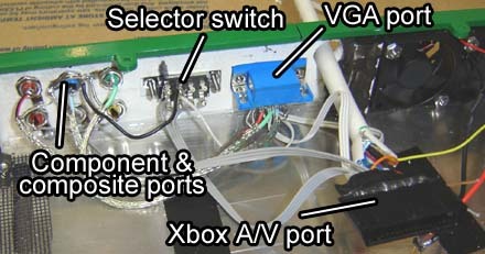
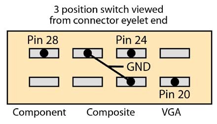
To the left of this is the big audio / video port. Since this port is fairly thin it won’t get in the way, and since it has so many pins it would be quite difficult to remove if you tried. Connections to it can be made via a hacked A/V cable (as with our Xbox 360 VGA hack) or by soldering to the points on the bottom of the board. More on this, as well as removing and rewiring the big power input jack, in Part 2.[/size]
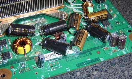
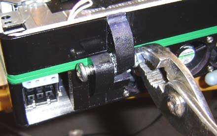
Capacitor Flattening
Even in this high-tech age of supersonic jets and microwave ovens many electronic devices still employ large electrolytic capacitors (“caps” for short). These are the can-shaped objects on a circuit board, usually colored blue or dark brown, and are usually the largest components as well. While we can’t remove them we can “flatten” them over to save some vertical space.
[size=25]Flattening caps:
-
Decide in which direction you’d like to flatten the cap. Keep in mind that if you’re flattening many caps you’ll need to make sure there’s going to be room to lay them all down.
-
Heat up the leads on the cap at the bottom of the motherboard (also called the solder side). Once they’re hot, you can bend over the cap. You can heat one lead, bend the cap a bit, heat the other lead, bend it, wash rinse repeat until the cap is tiled over on its side.
-
In some cases you may need to move the cap and not just bend it over. Desolder the cap and then use small bits of wire to attach the leads to the original spot.
[/size]

Be sure to check polarity when working with caps. On the motherboard one of the leads will be marked with a “+”, this is positive. The other lead may have a white stripe as shown above, this is negative. On the cap they’ll be a strip on one side or end – this indicates the negative terminal. Check that you rewire caps correctly. Doing them wrong can result in a 3 red lights of death scenario, though if you go in and fix the caps you’ll be ok. (So the 3 red lights aren’t always a death knell.)
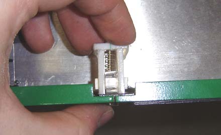
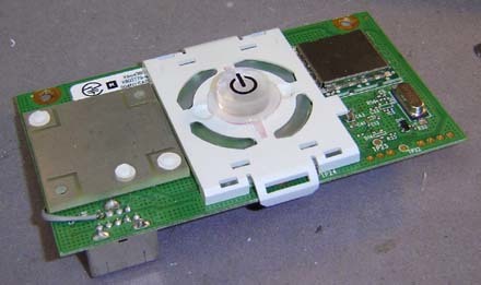
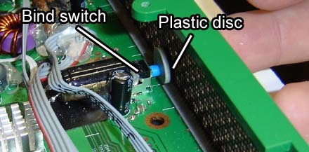
Hacking up the WiFi module
Next let’s hack up the worth-its-weight-in-gold WiFi module. Like many electronics these days, it’s literally glued together (which is why we don’t feel bad about our own hot glue fetish). It does take a bit of work to crack it open, though.
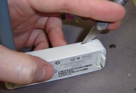
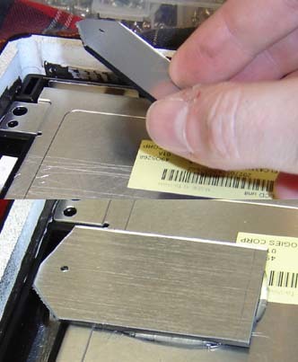
Start by using an X-Acto knive to cut a groove along the seam of the module on one side. Make several cuts until the groove is deep enough to fit a screwdriver inside.
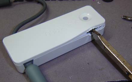
Next, as you may have guessed, stick a flat headed screwdriver in there and twist. This should pop open at least a portion of the shell. Once you have a bit of purchase you can wedge the rest of the shell off. Just don’t push the screwdriver in too far or you may damage some of the components.
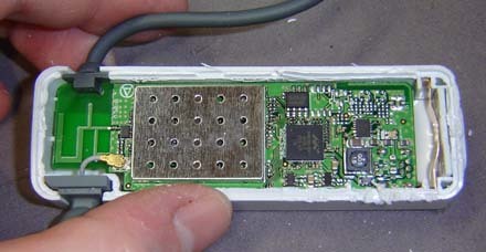
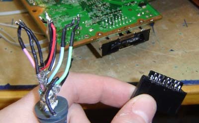
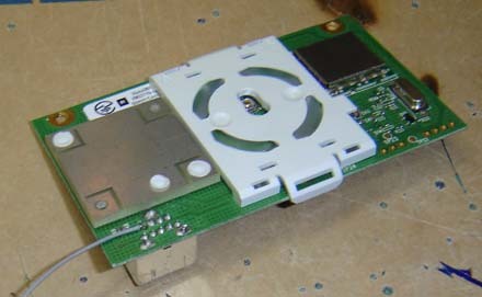
[size=25]Here’s the WiFi module with the shell opened. Not much too it really. Not let’s rewire the plugs to make it easy to use in a laptop portable.
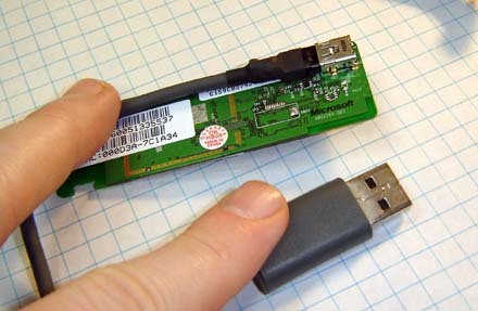
Here’s the original USB port. As you can see it plugs into the PCB via a mini-USB port, similar to a digital camera. Desoldering this port would be a bit tricky, so we’re simply going to attach new wires for the USB connection on the other side of it.
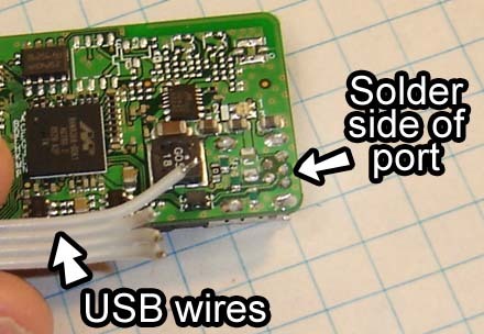
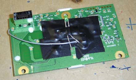
Shown above is the solder side of the mini-USB jack.
-
Using a multimeter, test the each pin inside the big USB jack while it’s connected to this PCB to see which pins on the back of the board are which.
-
To identify them, first find which pin on the big USB port is ground. This should connect to all ground points / shielding on the WiFi PCB, including the shielding of the mini-USB jack itself.
-
Once you’ve found ground, the next 3 pins over are Data +, Data - and then +5 volts.
Solder a piece of ribbon cable to the pins on the mini-USB port and mark the opposite end of the cable for future reference. Typically we suggest black magic marker for the ground wire and red for +5 volts.
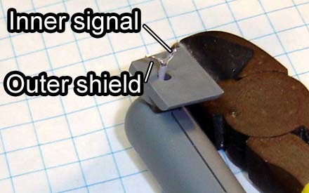
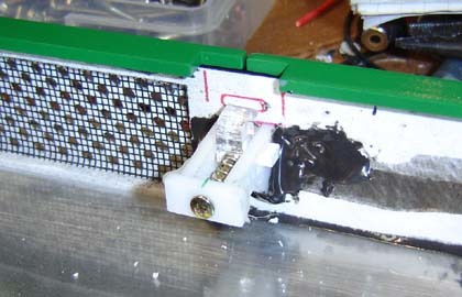
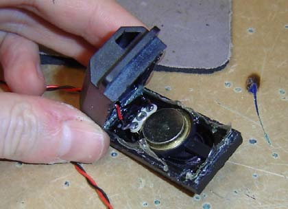
Next let’s extend the WiFi antenna wire. It starts out fairly short but with some careful modding we can change that.
-
Cut the wire at the middle section. This wire contains an outer shield (ground) and an inner coated wire which is the signal itself. This is very much like the WiFi we hacked back during the Wii laptop tour de force.
-
Strip a small bit of plastic off the inner wire and dab some solder onto the wire. Twist the stranded shielding wire together and solder it into a single piece as well. This is the kind of work where you’ll be glad you used a low wattage iron and not something that melts everything within a two foot radius into mush.
-
Solder a length of wire to each of these connections. For best results cover each connection with a bit of thin heat shrink tubing (available in the electric aisle of your friendly neighborhood hardware store).
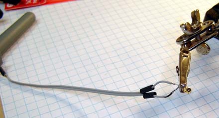
Re-attach the snap connector to the other end of the wires in the same fasion. Take care with this type of soldering since with the short existing wire there’s not much room for mistakes.
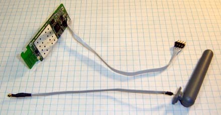
The hacked WiFi module. Note on the right side I’ve attached a 4 pin male header to the end of the USB wire. This will allow me easy connections to the rest of the motherboard further along in this project.[/size]
Modding / reattaching the DVD and hard drives
[size=25]Now let’s modify the DVD drive to fit in a smaller case, and prep the hard drive as well.
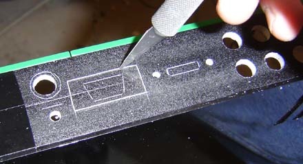
Start by using the Dremel cutoff wheel to remove the extra length of the 4 black plastic posts on the bottom of the DVD drive. Cut them off so they’ll flush with the base of the drive. The holes remain inside the post, allowing us a way to secure the drive to the final case. A size 8 screw will fit tightly into it.[/size]
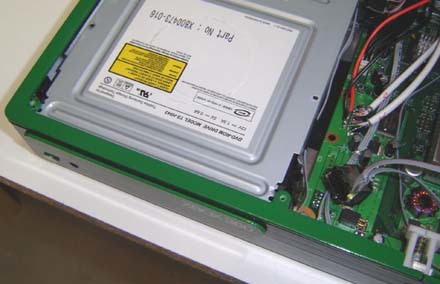
Extending SATA cables for the DVD and hard drive
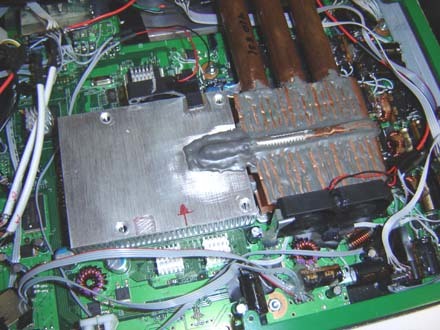
[size=25]In the original Xbox 360 the DVD drive sits atop the GPU heatsink and has a stubby SATA cable for its connection, along with a power cable very similar to the one for the DVD in the original Xbox.

The stubby SATA cable from the 360.
To place the DVD drive beside the motherboard for a laptop we’re going to need a longer SATA cable. One option is to simply buy one, but even a short cable might be too long and bulky for the confines of a case. Here’s how to hack the existing cable into a longer one:
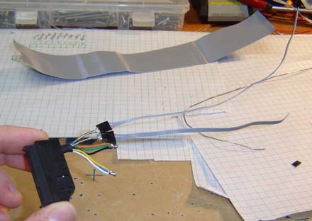
- Start by cutting the SATA cable in half length-wise. Note that the cable is in 2 halves side-by-by, one half is the A+ A- signals, the other is B+ B-. You can peel these halves apart like string cheese, which is fairly tasty unless it’s sat in your lunch pail too long.
- Using an X-Acto knife, carefully slice away about 1/2-inch of the plastic covering. This will reveal a tin foil like material.
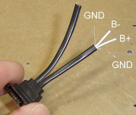
Carefully peel this away to reveal 2 bare wires (both are ground) and 2 coated wires (data signals).
Solder a piece of solid wire thin ribbon cable with 4 strands to the SATA wires. This preserves both the ground signals and the data (either A or B). Use a minimal amount of solder for the connections. Insulate the connections and repeat the procedure for the other half of the cable.
Reconnect the other end of the cable to the ribbon cable in the same way. To place the DVD player as seen in this laptop you’ll need to extend this cable by about 4 to 5 inches. The cable should now be ready to go![/size]
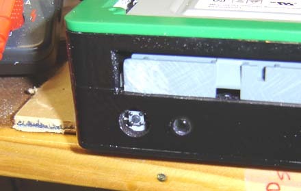
DVD drive power connector
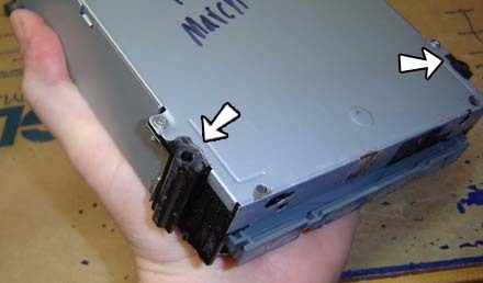
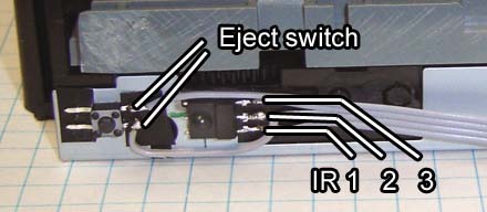
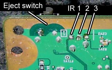
[size=25]The other cable going to the DVD drive is the power connector. It also includes an “Eject” signal.
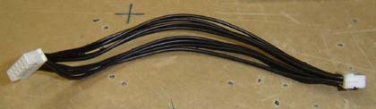
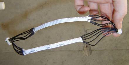
This consists of a group of black wires with a white plug on each end. It’s longer than the DVD’s SATA cable but still, in stock form, not long enough to move the drive very far. Note that the pinouts at both ends of the cable are the same, thus the wires “flip”, or cross each other from end to end. You can tell which way the cable is meant to be inserted by the small tabs on the side of the plug. More on this later.
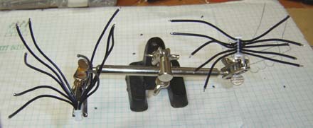
The cable cut in half. Doubles as a modern art spider.
Cut the power cable in half. Don’t worry about keeping track of which wire goes to what, it’s pretty straightforward. Strip a bit of plastic off the ends of the wiring and “tin” them with a bit of solder.
-
Cut (2) lengths of ribbon cable with 5 strands each. About 5-inches long should be good.
-
Solder each of the ribbon cables to the 5 wires on both sides of the plug, as shown above.
-
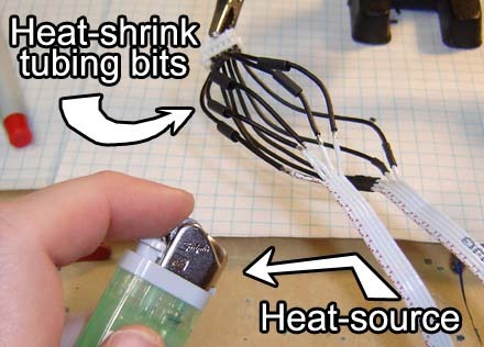
Insulate the wires with electric tape or small bits of heat shrink tubing. Of course you’ll need to remember to slide the tubing on before you make the connection. Regardless, heat shrink tubing gives it a nice clean look when done. We usually do ours with a lighter, the tubing shrinks before the wires burn.
-
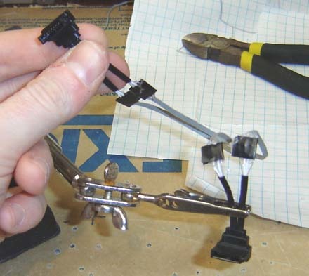
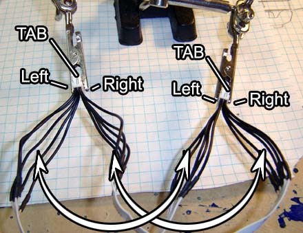
Connect each of the plug ends to each other with the ribbon cable. In this photo the tabs are placed as such to have their tabs both on the right, to ensure the connections are made correctly.
-
Note that the plugs are the same shape and have the same pinouts. Thus, the 5 wires on the “Left” side of the first plug connect to the 5 wires of the “Left” side of the second plug. This is what causes the wires themselves to “flip” or criss-cross between the cables.
The finished extended DVD drive power connector
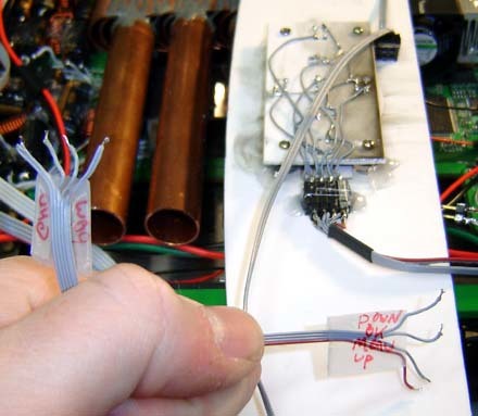
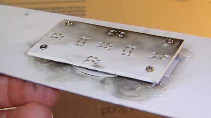
Hard Drive Connector
[size=25]Now it’s time to extend the connector for the hard drive. This is similar to the DVD method but we have to determine some of the pinouts manually.
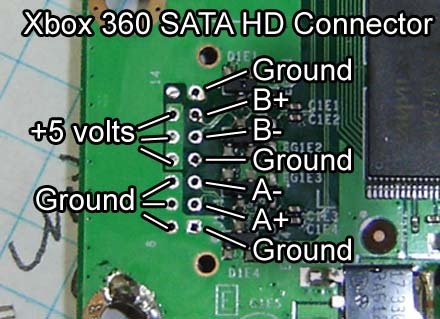
Above you can see the pinouts for the 360’s hard drive. There’s really only 6 wires to make the connection since most of the pins are ground. For this example we’ll use some standard size stranded ribbon cable for the ground and power, and thin, solid Ultra ATA ribbon cable for the data, like we did with the DVD drive.
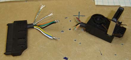
You can take apart the Xbox 360 Hard Drive enclosure with the same type of tools required for the main case itself. Inside you’ll find a 2.5-inch SATA laptop-style drive, a power / data plug going into it (item above on the left) some short wiring and then the plug which goes into the top of the Xbox (right).
-
Cut the wires off close to the Xbox plug end. We’ll be reattaching them by color code and pin testing, so no need to check how they connect on the Xbox plug.
-
Twist and solder together the white, blue and yellow wires - these are all +5.
-
Likewise, connect black, green and orange together, these are all ground.
-
As with the DVD drive’s SATA cable, peel back the foil on the other wires to reveal the data lines and their ground wires. Unlike the DVD cable it’s not very clear how to rewire the data lines, we’ll cover that shortly.
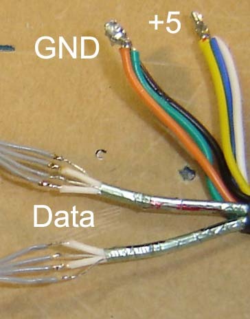
As with the DVD drive, solder a piece of 4-strand ribbon cable to each data strand. 2 of the wires will be ground, 2 data. We’ll determine which signals they are in the next step.
Here’s what the extended hard drive SATA plug/cable should look like. We’ve used a bit of electric tape to insulate the data connections, thin heat shrinking tubing would have also worked if we would have had some around. For this project we’ve added about 5-inches of length, and without the aid of prescription drugs.
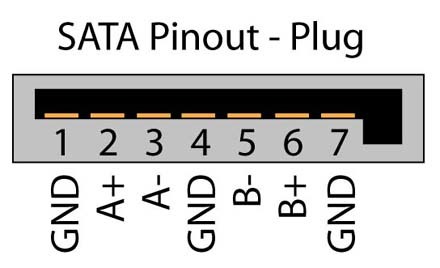
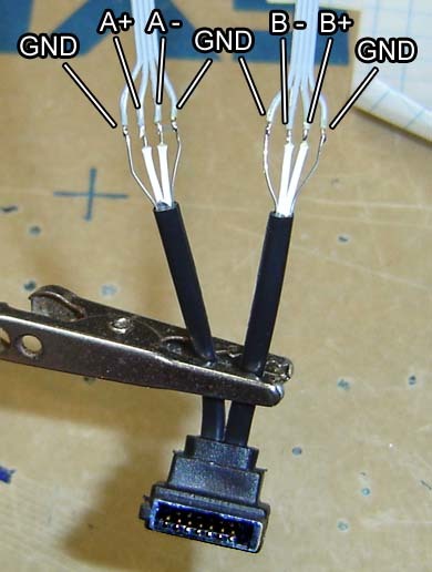
Pinout of a SATA plug.
-
We need to discover what the pinout is of the wires on the other side, but it’s kind of hard to fit the probes of a multimeter into a jack like this. Use a small bit of stiff wire (such as that clipped off a resistor) to insert into each pin of the jack for easy testing.
-
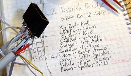
Use the multimeter to test which wires at the end of the newly extended cable are A+, A-, B- and B+. You may find it handy to label them using different colored magic markers, or by putting a bit of Scotch tape on the end of the wire and making it with a pen.
-
Solder the cables to the motherboard using the pinouts shown at the beginning of this section, as well as making the +5 and ground connections.

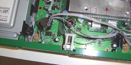
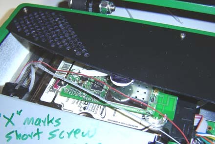
Here’s how the extended SATA/power cables should look when soldered to the motherboard. Notice how we’ve “doubled up” the ground and power with 2 stranded ribbon cable wires each. This ensure enough current gets through. Sure it’s just a 500mA laptop hard drive and not, say, an electic pizza oven, but it’s good to make sure anyway. Alternatively you could use slightly thicker gauge wire but that’s not always as convienent, and tends to be a bit stiff and unwieldy.
Also note that the 2 ground connections per data cable had been soldered to ground (lower connections on the left and rightmost sides). You can never have enough grounds!
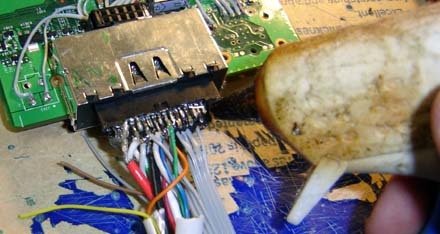
Once you’ve had a chance to make sure that it’s working properly it’s a good idea to “lock down” the wires with some hot glue. You don’t need to cover the connections, just glue the wires down someplace nearby. What this does is keep the wires from pulling or breaking free of the motherboard since the “hinge point” becomes where you’ve glued them down, not at the connection point. A good general-purpose tip for any kind of electronics hacking.
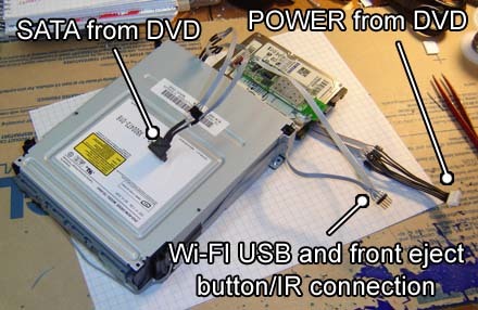
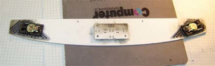
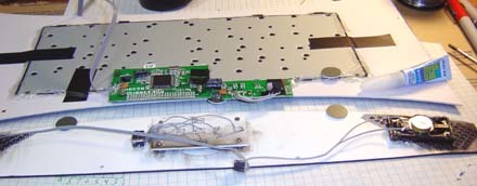
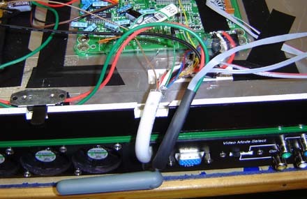
Here’s the final combo unit. We have the DVD drive with the hard drive attached at the rear. On top of this is the WiFi module we hacked earlier, and everything has convienent ports for connecting to the main motherboard. This modular approach is a big help when assemblying and troubleshooting a unit. The extra time it takes to add plugs and ports now will save time later when you don’t have to desolder or cut wires later.[/size]
[/details]
You can find the remaining two parts on the second page of this thread!


